For Borings What Info Do You Need to Know
Contents
- ane
- 1.1 Number of borings to collect
- 1.2 Historical site information
- one.3 Types of soil sample drove methods
- 1.4 Disturbed versus undisturbed soil samples
- 1.5 How to lodge a soil boring
- 1.6 Data gathered from soil samples
- ane.7 Interpreting soil boring logs
- 1.8 Samples for laboratory testing
- ane.9 Restrictive layers in soil profiles
- ane.x Soil exploration reports
- 1.11 Additional resources
- 1.12 References


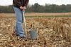
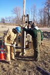
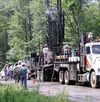
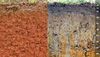
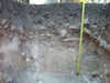
Example soil boring. Photo courtesy of Barr Engineering science.

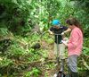
Example of direct push technology used to collect a soil sample.
Caution: The MPCA Highly recommends field determination of soil infiltration rates. Meet Determining soil infiltration rates. If soil borings or soil pits are utilized, it is Highly recommended a certified soil scientist or geotechnical engineer interpret the borings.
Knowing the soils in the area of a proposed infiltration best management practice (BMP) helps determine the suitability and blueprint of the BMP. Soils determine how rapidly stormwater volition infiltrate, affect plant growth, and affect the fate and ship of pollutants. Section 16.ten of the Construction Stormwater general permit states "Permittees must provide at least one soil dull, test pit or infiltrometer exam in the location of the infiltration practice for determining infiltration rates". The Minnesota Stormwater Manual recommends that soil borings or pits be dug to verify soil types and infiltration capacity characteristics and to make up one's mind the depth to groundwater and boulder.
This commodity presents a discussion of soil sampling, soil borings, and interpreting soil information.
Caution: Objectives for collecting soil borings for stormwater infiltration practices differ from objectives for collecting borings for structural engineering science purposes. Identification of low permeability or restrictive layers in soil is critical to proper design and construction of infiltration practices. In particular see the sections on How to lodge a soil wearisome and Restrictive layers in soil profiles.
Caution: Information technology is Highly Recommended that soil borings be extended a minimum of 5 anxiety below the bottom of the proposed infiltration exercise and that the about restrictive soil layer be considered in estimating infiltration rate.
Warning: The Construction Stormwater General Allow states "Permittees must provide at least ane soil boring, examination pit or infiltrometer test in the location of the infiltration exercise for determining infiltration rates"
This video provides an example of the touch on of fifty-fifty thin layers of clay on infiltration.
Number of borings to collect
The recommended number of borings is shown in the folowing table.
Recommended number of soil borings, pits or permeameter tests for bioretention design. Designers select one of these methods.
Link to this table
| Surface surface area of stormwater control measure (BMP)(ft2) | Borings | Pits | Permeameter tests |
|---|---|---|---|
| < chiliad | 1 | ane | 5 |
| m to 5000 | 2 | 2 | 10 |
| 5000 to 10000 | iii | 3 | fifteen |
| >10000 | iv1 | ivi | 20two |
1an additional soil boring or pit should be completed for each additional 2,500 ft2 above 12,500 ft2
2an additional five permeameter tests should be completed for each additional five,000 ft2 above fifteen,000 ftii
Historical site information
Prior to ordering a soil investigation, it is highly recommended that historical records are evaluated for the site. What other utilize(s) has the site had? Are historical soil borings available for the site? Could site soils be contaminated? A listing of possible site soil constraints and boosted information can be constitute here. This page provides a summary of useful information sources for investigating the history of a site.
The more variable the site history, the greater variety of soil types you may expect to detect. For example, a rural 1 acre site that has always been farmed volition probably have more consistent soils from one location to the next compared to an urban ane acre site which has had many different uses, including importation of fill up materials. An urban site with many previous uses may require a larger corporeality of soil investigation to properly identify the soil contour.
Types of soil sample collection methods
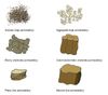
There are several types of soil sample collection methods which tin be used to decide soil characteristics. Sample collection methods are listed in the following tabular array from simplest/quickest/cheapest to complex/slower/expensive. The tabular array describes advantages and limitations and provides references and photographs for each of these methods.
- Soil probe
- Paw held or machine auger
- Excavation test pit or trench
- Direct push applied science (DPT)
- Rotosonic drilling
- Soil boring (hollow stem auger or HSA method)
Of these vi types of soil sample collection methods, soil borings are highly recommended. Soil borings provide the greatest amount of information. Knowing existing conditions equally a result of proper soil investigation allows the design team to develop an authentic pattern and cost gauge prior to bidding or construction. Finding unexpected soil atmospheric condition during structure can event in time delays and costs associated with modifying the pattern.
Summary of drilling methods to collect soil samples for infiltration basins. Click on an image to enlarge.
Link to this table
| Drilling Method | Clarification | Sample Collection Possible | Depth | Advantages | Limitations | Photograph reference/credit | Example Photo |
|---|---|---|---|---|---|---|---|
| Soil Probe | Soil probes are a basic form of soil sampling, used to collect shallow or surface samples by pushing a T-shaped probe into the footing. The probe cuts a cadre sample smaller than the bore of the probe torso. The sample can also exist collected within a liner inside the probe. | Pocket-sized diameter soil surface profile | ≤ 3 feet | Cheap Quick Easy to use | May not be able to collect enough information to decide if infiltration is possible due to depth and express soil information nerveless. Unable to perform blow counts.1 | Iowa Land Academy - Academy Extension | |
| Paw held or machine auger | The auger is held vertically and is driven into the ground and rotated by the handle while applying leverage. At every 30 cm of depth penetrated, the auger is taken out and the samples of the soils are nerveless separately for test. This method works best in loose materials ranging from clay to sand to gravel. | Bag/jar samples of material | ≤ 50 feet | Inexpensive, Easy to use. Big selection of auger types | Only suitable for unconsolidated deposits (loose materials) Dull compared to other methods Equipment tin be heavy. Unable to perform blow countsone. | University of New Hampshire - Institute for the Study of Globe, Oceans, and Space | |
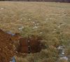
| Excavation Test Pit or Trench | A pit or trench is dug manually or with an excavator to depth desired in guild to visually observe subsurface soil conditions. | Grab samples or majority samples of textile | ≤ 20 feet | Quick, Easy to do, Shallow exploratory drilling method | Must be onsite during excavation to coordinate locations and depth as well as observe subsurface soils and behavior, taking photos and soil samples Shallow form of subsurface drilling Must exist cautious of collapsable soils when digging Requires back make full and compaction. Unable to perform blow counts1. | U.s. Department of Agronomics - Natural Resources Conservation Service New Hampshire | |
| Directly Button Applied science (DPT) | Geoprobe or Strataprobe is pnuematic hammer driven with continuous sampling into plastic tubes. Accident counts1 are not provided through this method. Single tube and dual tube systems are bachelor. | Bag/jar samples of material | usually upward to 60 feet but tin go to over 100 feet | Minimal to no cuttings Quick and efficient Small-scale, relatively mobile rig Continuous sampling | Unable to perform blow counts1 | Minnesota Pollution Control Agency | |
| Rotosonic | Rotosonic drilling is a method where continuous samples are taken. It is adept for penetrating through most formations, merely due to the ground disturbance, is not suitable for collecting undisturbed samples. Samples are brought out of the subsuface in articulate plastic sleeves. | Bag samples of material | >100 feet | Continuous sampling Quick and efficient Produces picayune to no waste product | Mobilization cost tin be expensive. Unable to perform blow counts1. | United states of america Geological Survey - Eastern Mineral and Ecology Resources Scientific discipline Center | |
| Standard Penetration Examination (SPT) using Hollow Stem Auger (HSA) drilling method | Augers human activity as casing for borehole (foreclose caving) Center of augers is hollow for sampling | Handbag/jar sample Split-spoon (or other disturbed samples) Thin-wall samples (or other undisturbed samples) | >100 feet | Augers practice not need to be removed to sample Can be used to a higher place and below water table. Can collect blow countsane. | Heaving sands may clog the hollow stem auger. Can exist slow when drilling in soils with cobbles and boulders. | U.Southward. Department of Transportation - Federal Highway Administration | |
1 For information on blow counts, link hither or link here for tabular array illustrating blow counts.
Disturbed versus undisturbed soil samples
There are two categories of soil samples, disturbed and undisturbed.
- A disturbed sample does non retain the in-situ construction of the soil. These types of samples can exist used for classification tests such as the grain size analysis which is described in greater detail below. There are generally 3 types of disturbed samples that can be nerveless during an investigation.
- Bulk samples. These can be a modest grab sample that fits into a naught-lock pocketbook. Larger samples can be collected in 5- gallon buckets. These samples are usually auger cuttings from the meridian 5 feet, or taken from an earthworks test pit or trench.
- Split-spoons samples are 1-3/8 inch diameter cylindrical columns of soil obtained using a split-spoon sampler. The sampler is pounded into the soil in three or four half-dozen-inch drives using a driving weight assembly. The number of hammer blows needed to pound the spoon 6 inches in depth is chosen the blow count and is recorded on the boring logs. The 6 to 12 inch and 12 to 18 inch blow counts are added and recorded as the due north-value for that divide-spoon. Gravel and cemented soils take high blow counts while clay and soft soils will have low accident counts. Split up-spoon samples are taken during a soil boring. This type of sample volition give the most relevant information in determining soil suitability for an infiltration BMP.
- Continuous sampling methods provide a complete tape of the soil beneath a drilling site. Samples are usually nerveless in plastic 5-foot liners. Generally this sample method is not necessary to determine infiltration potential at a site equally they do not allow collection of blow counts.
- Undisturbed samples are recovered completely intact and the in-situ structure and stresses are not modified in any way during drove. Samplers used to collect relatively undisturbed samples include Thin-wall, Modified California, Piston, and Pitcher. Undisturbed samples are generally not collected when trying to decide infiltration potential at a site as they practice not allow collection of accident counts.
How to order a soil tiresome
Having a geotechnical engineer/technician (engineer) present during drilling investigations is highly recommended equally they specialize in field reconnaissance, coordinating and directing the drillers, logging boreholes, and collecting soil samples. Having an engineer onsite during drilling investigations will price more initially, but if subsurface information is inaccurate or inadequate, a greater number of assumptions need to be incorporated into the design, which increases the potential for negative impacts later in the design life and/or costly surprises during construction.
If an engineer cannot be onsite during drilling investigations, good communication with the drillers prior to performing soil borings will help ensure the most valuable data is obtained. It is important the drillers sympathize the purpose of the investigation. Explain that drilling is being done to find soils indicative of restrictive layers; i.eastward. soils that inhibit the flow of water. Listed by most restrictive to least restrictive, these soils are: clay, silt, sand, and gravel. Provide drillers with the following guidance:
- If recovery in a split-spoon sample is less than six inches, drill 2 feet deeper and perform another split-spoon sample.
- If a circumscribed layer is establish, or there is depression recovery in a split-spoon, reduce sampling intervals to every 2 anxiety. Record the presence of the most restrictive layer, fifty-fifty if that material is not the most abundant in the separate-spoon sample.
- If depression recovery is encountered, explain in the field notes why the driller thinks this is happening (i.e. gravel in the shoe of the split-spoon)
- Blow counts or "Due north" values establish during a Standard Penetration Examination (SPT) are critical to determining the presence of restrictive layers. For information on standard penetration tests, run into here
- If soil boring auger refusal is encountered prior to depth desired, offset approximately v feet from initial borehole, blind -drill (continuous drilling without soil sampling) to refusal depth, and continue drilling/sampling from that point. Note in that location will be an additional cost acquaintance with the kickoff and blind drill. If the 2d attempt results in the same refusal every bit the outset, the driller should phone call the engineer to inquire virtually side by side steps immediately, prior to leaving the site. During that telephone call, ask drillers to describe why they think refusal has been met and, if necessary to drill deeper, hash out culling drilling methods or an additional offset.
- Ask the driller to include soil type, recovery, accident counts, and presence of water in their field logs, and asking a copy of their field logs.
- It is highly recommended that the drillers utilise a standard form (attached). If they do non use a standard form, request to see their form prior to drilling and suggest modifications as necessary.
- To the extent possible, the concluding boring logs should contain information listed in the table Summary of Data to Include on a Boring Log (see below).
Information gathered from soil samples
Soil samples aid provide a general subsurface profile and tin can be used to mensurate engineering backdrop, including those properties indicating the presence of a restrictive soil layer. When a soil deadening is performed to determine if a site is suitable for infiltration, the following data should be requested from a soil boring visitor or geotechnical engineer (see attached Tabular array 2 for greater particular):
- Boring name
- Project proper name/project number/client/nearest metropolis or canton
- Boring coordinates (location) and ground surface superlative (local reference to a fixed signal on the site is adequate)
- Get-go / End appointment and time
- Site conditions at time of sampling, including conditions
- Type and depth of boring
- Type of drilling method
- Sampling method and sample type
- Sample recovery
- Soil Density or Consistency
- Soil Color (includes mottling or redoximorphic feature colour, abundance, size and dissimilarity)
- Grain size adamant by Particle Size Distribution (PSD) lab test
- Particle shape
- Classification (ASTM D2487-xi): USDA, AASHTO, and USCS (with USCS being the most commonly used)
- Sedimentary structure
- Layer boundaries and thickness (transition in colour or betwixt two different types of soil)
- Blow Counts
- Depth to bedrock, and/or refusal
- Depth to groundwater (indicated during drilling by wet or saturated soil moisture content and afterwards drilling by recording the water level in an open borehole typically measured after 24 hours)
- Plasticity (plasticity of a soil is its power to undergo deformation without cracking and is greatly influenced by the particle size, h2o content, and aging)
- Moisture
- Inclusion is used to describe the secondary mineral component in a soil sample
- Topsoil (A Horizon) thickness
- Photos
Summary of data to include on a boring log. To enlarge an image, click on the image.
Link to this table
| Include on log | Clarification | Example / Photo |
|---|---|---|
| Boring name or number | Important to identify and distinguish each boring with a unique name | Well-nigh borings first with B or BH and end with a number Example: B-01 or BH01 |
| Project proper noun, number, client, and city or county | Data is used identification purposes and for sample storage | |
| Slow coordinates and ground surface height | Each hole should exist located and verified with coordinates in instance of discrepancies If possible, record basis surface elevation with GPS Locations should be shown on a figure or map | Include Datum (NAD29 vs NAD83, NAVD 1929 or NAVD 1988) Understand coordinate systems. For example. UTM is in meters while Lat/long is in degrees or deg/min/sec |
| Outset and end date and time | Helpful for tracking how long drilling is taking per borehole A known date can aid place the project for future reference | |
| Blazon of drill rig and boring depth | Will be used to determine the hammer efficiency if performing blow counts. Examples include:
| |
| Drilling method | Record method used or depth where at that place is any modify in the method beingness used. Unlike drilling methods may require dissimilar sampling techniques or procedures. Drilling methods include: Hollow Stem Auger, Straight Push Technology, Mud Rotary, Rotosonic, Air Rotary, ODEX. | |
| Sampling method and sample blazon |
| |
| Sample recovery | Record recovery of samples for comparison to length of drilled sample Note assumed reasoning for poor recovery (i.e. bedrock, gravel stuck in splitspoon) | For case, the carve up-spoon was pounded 18" but but 10" of soil was recovered in the sampler |
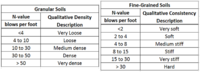
| Soil Density or Consistency | Unlike characterization of coarse and fine grained samples Based on N-value of sample | |
| Color | Most colors should be earth tones with descriptors. Include all mottling or redoximorphic characteristic colors. Note iron staining or oxidized areas for indication of previously wet soil that has been stale out | |
| Grain size | For granular samples merely (not for silts and clays). Can be called: very fine-, fine-, medium-, coarse-, or very coarse-grained | |
| Particle shape | Can be angular, subangular, subrounded, or rounded. Important for understanding deposition surround and weathering of soil. | |
| Soil nomenclature |
| |
| Sedimentary structure | Refers to bedding and laminations in the soil. Provides insight to origin of soils or potential weathering or chemical reactions experienced. Provides insight to geologic hazards (i.eastward. weak soil layers, collapsibility) | Source: Ontario Ministry of Agriculture Food and Rural Affairs |
| Layer boundaries and thickness | Annotation stratigraphy breaks on logs. Unless transition is obvious while drilling, assume it is halfway betwixt sampling intervals. | Source: Texas State - center for Archaeological Studies |
| Blow Counts | The number of hammer blows to pound the separate-spoon six, 12, 18, and 24 inches into the soil. The 6 to 12 and 12 to eighteen inch blow counts are added and recorded as the n-value for that split-spoon. "Refusal" or termination of borehole occurs if the hammer does not advance for >50 blows/vi inches. Note the advancement (e.grand. 50/two"). | |
| Depth to bedrock and/or refusal | "Refusal" or termination of borehole occurs if the hammer does not accelerate for >l blows/half dozen inches. Note the advancement (e.g. l/2"). Note refusal on logs. Annotation sample recovery if refusal is reached in a carve up spoon interval. | |
| Depth of groundwater | Tape during and after drilling Note perched layers of water in sand or lignite. Record cave-in depth in unstable boreholes. Note if h2o isn't encountered. Saturated silts will accept high dilatancy. | |
| Plasticity | Plasticity helps determine if a clay is lean (low plasticity) or fat (high plasticity). Is very dependent on wet content (i.e. dry fatty dirt can seem like it has low plasticity) | |
| Wet | Provides indication of water table. For each sample place if it is moist, wet, or saturated. | |
| Inclusions | Used to draw the secondary components in a soil sample.
| |
| Topsoil thickness | Helpful to know how much topsoil stripping may be necessary. Note organic fabric if present or not. | |
| Photographs | Pictures should be taken of each borehole location. Take photo of stake and all four directions. Tape and photograph any crop damage. Photograph any interesting soil samples that may be of concern |
Interpreting soil tedious logs
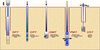
Deadening logs can be presented vertically or horizontally. Examples of logs for four of the drilling methods previously presented are attached.
- Excavation Test Pit or Trench log
- Directly Push Technology (DPT) log
- Rotosonic log
- HSA soil boring log (horizontal and vertical)
Note that layer boundaries are well divers on each of these logs making it easy to place the transition between different soil types. All the data discussed in Tabular array ii is presented on the logs too as laboratory testing results.
- Examples of soil boring logs. Click on an image to enlarge.
-
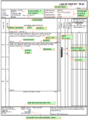
Log of examination pit TP-01 -
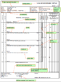
Log of geoprobe DPT-01 -
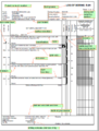
Log of wearisome R-01 -
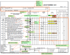
Log of boring B-01 -
Log of deadening B-01
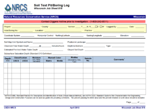
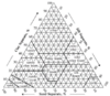
Note that each of the example logs to a higher place utilize the United Soil Nomenclature System (USCS). While this is the nearly ordinarily used nomenclature organization on tedious logs, other systems, such equally the Usa Department of Agronomics (USDA) classification organisation, may exist used. An example bare form that allows for both the USCS and USDA classifications is shown in the figure to the right (Source: USDA-NRCS). Comparisons betwixt the USCS and USDA classifications are shown in the post-obit table.
Design infiltration rate as a role of soil texture for bioretention in Minnesota
The values shown in this table are for uncompacted soils. This tabular array can be used as a guide to determine if a soil is compacted. For information on alleviating compacted soils, link here. If a soil is compacted, reduce the soil infiltration rate by 1 level (e.thou. for a compacted B(SM) employ the infiltration rate for a B(MH) soil). Link to this table
| Soil texture (USDA classification) | Corresponding Unified Soil Classification | Respective hydrologic soil Grouping (HSG) | Design Infiltration Rate (in/60 minutes) |
|---|---|---|---|
| Gravel, sandy gravel, and silty gravels | GW – Well-graded gravel or well-graded gravel with sand GP – Poorly graded gravel or poorly graded gravel with sand | A | 1.63 |
| Sand, loamy sand, and sandy loam | GM – Silty gravel or silty gravel with sand SW – Well-graded sand or well-graded sand with gravel SP – Poorly graded sand or poorly graded sand with gravel | A | 0.viii |
| Silty sand | SM – Silty sand or silty sand with gravel | B | 0.45 |
| Silt loam, loam | ML – Silt OL – Organic silt or organic silt with sand or gravel or gravelly organic silt | B | 0.three |
| Sandy clay loam | GC – Clayey gravel or clayey gravel with sand SC – Clayey sand or clayey sand with gravel | C | 0.2 |
| Clay, clay loam, silty dirt loam, sandy clay, and silty dirt | CL – Lean clay or lean dirt with sand or gravel or gravelly lean dirt CH – Fat clay or fat clay with sand or gravel or gravelly fat clay OH – Organic clay or organic clay with sand or gravel or gravelly organic clay MH – Rubberband silt or elastic silt with sand or gravel | D | 0.06 |
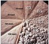
Samples for laboratory testing
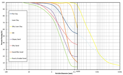
Example of a particle size distribution (PSD) bend, which shows the pct of soil from a sample passing through a sieve of known bore. For instance, in a sand, only virtually v percent of the sample passes through a 0.1 millimeter diameter sieve, while for a silt, 80 percent pass through.
Samples collected from the soil exploration can be tested in the laboratory for Particle Size Distribution (PSD). This examination is critical to determining the most limiting soil layer with respect to infiltration. A disturbed or bulk sample is advisable for this test. The PSD test was developed to allocate a soil particle based on its size according to the particle's ability to laissez passer through a series of standard sieves. A sieve is a carefully manufactured mesh of wires with a specified opening size. The ASTM D2487 standard is the about commonly used for particles retained on the #200 sieve or greater than 0.003 inches (0.075 millimeters) in bore. A hydrometer analysis tin exist performed on particles smaller than the #200 sieve following ASTM D422 standard, only is generally not necessary for infiltration analysis. If a large per centum of soil sample particles are passing the #200 sieve, infiltration is not recommended. PSD curves are created from the sieve and/or hydrometer results which provide the information needed to classify a soil and determine if the soil is poorly-graded (does not have a skilful representation of soil particle sizes) or well-graded (has a practiced representation of soil particle sizes). An example of a PSD curve is shown to the right.
Restrictive layers in soil profiles
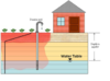
A restrictive soil layer is 1 continuous layer of soil that impedes the motility of water through information technology. A restrictive layer will also impede air movement and root growth. Bedrock, frozen soils, dense soils, cemented soils, saturated soils, and a clay layer are examples of restrictive layers. A restrictive soil layer is capable of perching groundwater higher up the layer. This video provides an instance of the impact of fifty-fifty thin layers of dirt in soil.
Infiltration is limited past the least permeable or most restrictive layer in the soil profile. The Minnesota Structure Stormwater general permit prohibits infiltration in areas with less than three feet of separation distance from the bottom of the infiltration arrangement to the elevation of the seasonally saturated soils or the top of bedrock. Other published guidance found on the California Environmental Protection Agency State Water Resources Control Board website recommends that any restrictive soil layer constitute inside 10 anxiety of the lesser of an infiltration BMP should be evaluated by a Professional Engineer (PE) and approved by the City Engineer.
If a restrictive layer is found within x feet of the bottom of an infiltration BMP, the Project Engineer should evaluate whether the site is a good location for an infiltration BMP, or if another blazon of BMP would exist more successful. Items to consider include depth to restrictive layer, restrictive layer thickness, classification of soils above and below the restrictive layer, density of soils above and below restrictive layer, depth of wet and/or saturated soils (groundwater), depth of seasonally high groundwater, surface area hyrdrology, and size of watershed draining to infiltration BMP. Additional considerations when considering a site for infiltration can be found here in the Minnesota Stormwater Manual:
Soil exploration reports
At the end of a soil exploration programme, and when the soils collected from the field have been subjected to visual observation and laboratory testing, a soil exploration report is prepared for utilize in planning and design, clearly summarizing results and providing soil data (including boring logs). A larger exploration program will required a larger report while a smaller program might only exist summarized in a short technical memo. The items listed below should be nowadays in both types of reports, but the level of information or detail summarized volition vary.
- Telescopic and purpose of investigation
- Description of proposed development
- Geologic conditions of the site
- Summary of field exploration
- Groundwater conditions
- Laboratory testing
- Analysis of subsurface weather
- Design recommendations/anticipated structure problems
- Closure/limitations of the investigation
- Maps/figures
- Site location
- Location of borings with respect to the proposed structure
- Appendix A – Boring Logs
- Appendix B – Laboratory Test Results
Additional resources
Additional information most evaluating site soils tin can exist found in Site Evaluation for Stormwater Infiltration by the Wisconsin Department of Natural Resources Conservation Practice Standards (2004).
Information on soil investigations for petroleum contaminated sites include the post-obit.
- Soil and Ground Water Assessments Performed During Site Investigations. Guidance ocument 4-01.
- Soil Sample Drove and Assay Procedures. Guidance Document 4-04.
References
- Das, Braja M. 2006. Principles of Geotechnical Engineering. sixth Edition. Cengage Learning, Stamford, CT.
- Coduto, Donald P.; Yeung, Man-chu Ronald; Kitch, William A. 2011. Geotechnical Engineering Principles and Practices. second Edition. Pearson, Upper Saddle River, NJ.
- Terzahi, Karl; Peck, Ralph B.; Mesri, Gholamreza. 1996. Soil Mechanics in Engineering Practise. 3rd Edition. John Wiley & Sons, Inc.
andersonbremandes.blogspot.com
Source: https://stormwater.pca.state.mn.us/index.php/Understanding_and_interpreting_soils_and_soil_boring_reports_for_infiltration_BMPs
Enregistrer un commentaire for "For Borings What Info Do You Need to Know"